
Process Principle of Oil-Gas-Water Three-Phase Separator
During oil and gas production, the extracted fluid from the wellhead is not a single stream of oil or gas, but rather a complex mixture composed of crude oil, natural gas, and water. To enable subsequent processing and utilization, these three components must be efficiently separated, which is achieved using a three-phase separator.
1. Working Principle
The three-phase separator mainly relies on gravity settling, fluid dynamics, and interface control to achieve the separation of oil, gas, and water:
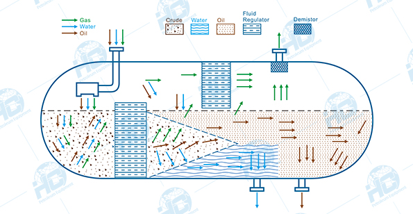
- Gas Separation: After the mixed fluid enters the separator, the flow velocity decreases sharply. Due to its lowest density, natural gas rises quickly and is directed to the upper gas outlet.
- Liquid Stratification: The denser water settles at the bottom of the vessel, while the lighter crude oil floats above the water layer, forming a clear oil-water interface.
- Interface Control: With the aid of level gauges and interface controllers, the oil, gas, and water phases remain stably stratified inside the separator and are discharged separately through their respective outlets.
2. Main Structural Components
A standard three-phase separator is typically composed of the following parts:
- Shell (Pressure Vessel): Designed in horizontal or vertical orientation according to process requirements, generally cylindrical in shape, with pressure-resistant and corrosion-resistant properties.
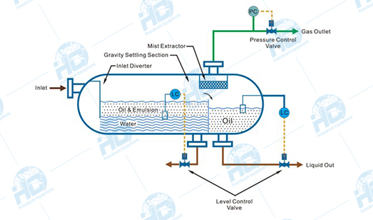
- Inlet Device (Feed Distributor): Distributes the high-velocity mixed fluid evenly and reduces impact.
- Gas Separation Section: Located at the upper part of the vessel, often equipped with a demister or cyclone separator to remove liquid droplets entrained in the gas.
- Liquid Settling Section: Located at the middle and lower part, where oil and water are separated by gravity.
- Baffles / Coalescing Devices: Extend the retention time of liquids, promoting the coalescence and settling of small droplets.
- Interface Control System: Includes level gauges, interface sensors, and automatic liquid discharge control valves to maintain stable stratification of oil and water.
- Outlet Piping: Separate outlets are provided for the gas phase, oil, and water.
3. Working Process
- Feed Diffusion: The mixed fluid enters through the inlet, and its flow rate drops sharply, causing most of the gas to immediately escape.
- Preliminary Gas-Liquid Separation: The gas enters the upper space, passes through a demister to remove entrained liquid droplets, and is discharged through the gas outlet.
- Oil-Water Stratification: Under gravity, the liquid naturally separates—water, being denser, settles at the bottom, while oil floats on top.
- Interface Control: The oil-water interface height is maintained by a level control system to ensure stable separation.
- Three-Phase Discharge: Gas, crude oil, and wastewater are discharged separately through their respective outlets and sent to subsequent processing stages.
Basic Specification Data
Separator can be designed as per client’s operation conditions depending on flowrate, temperature, pressure, working medium and other operation data. Most of the clients, prefer size of 42 in. x 10 ft. and pressure of 1440 psi,b for well test operation.
| Design pressure | Vessel size | Liquid Capacity | Dimensions (L x W x H) | Dimensions (L x W x H) | |||
| psi | bar | MPa | inch X foot | cm | bopd | ft | m |
| 800 | 55 | 5.5 | 34 x 8 | 86 x 244 | 3500 | 13 ft x 7 ft x 8.5 ft | 4.0 m x 2.1 m x 2.6m |
| 1440 | 99 | 10(9.93) | 30 x 10 | 76 x 305 | 3500 | 15 ft x 6.5 ft x 8 ft | 4.6 m x 2.0 m x 2.5 m |
| 42 x 10 | 107 x 305 | 10000 | 15 ft x 7.5 ft x 9 ft | 4.6m x 2.3 m x 2.7 m | |||
| 42 x 15 | 107 x 457 | 12000 | 20 ft x 7.5 ft x 9 ft | 6.1 m x 2.3 m x 2.7 m | |||
| 48 x 10 | 122 x 305 | 13000 | 15 ft x 8 ft x 9.5 ft | 4.6 m x 2.5 m x 2.9 m | |||
| 48 x 12 | 122 x 366 | 19000 | 17 ft x 8 ft x 9.5 ft | 5.2 m x 2.5 m x 2.9 m | |||
| 48 x 15 | 122 x 457 | 19000 | 20 ft x 8 ft x 9.5 ft | 6.1 m x 2.5 m x 2.9 m | |||
| 2160 | 149 | 15 | 24 x 10 | 61 x 305 | 1000 | 15 ft x 4 ft x 7.5 ft | 4.6 m x 1.2 m x 2.3 m |
| 42 x 15 | 107 x 457 | 12000 | 20 ft x 7.5 ft x 9 ft | 6.1 m x 2.3 m x2.7 m | |||
| 48 x 15 | 122 x 457 | 15000 | 20 ft x 8 ft x 9.5 ft | 6.1 m x 2.5 m x 2.9 m | |||
Vertical & Horizontal Three-Phase Separators
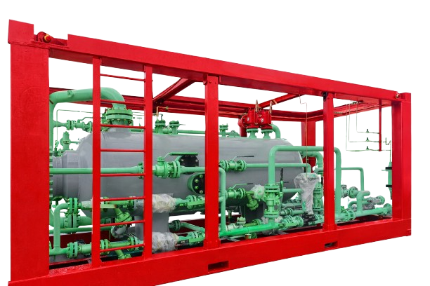
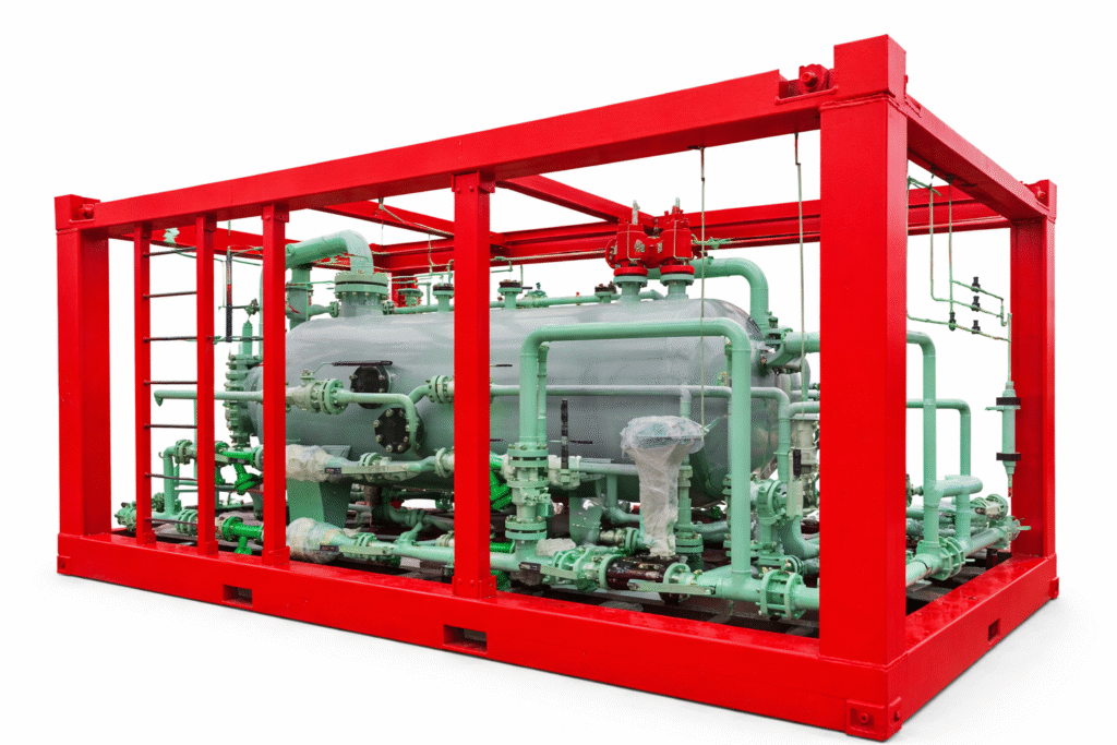
The horizontal three-phase separator has its vessel axis parallel to the ground, making it ideal for fluids with a high liquid-to-gas ratio or liquid-liquid separation. It offers longer horizontal sections for liquid flow and shorter vertical sections for gravity separation, making it perfect for well testing, production separation, and multiphase flow metering. It requires more horizontal space but is less affected by environmental factors like wind, suitable for both offshore and onshore applications.
The vertical three-phase separator has its vessel axis perpendicular to the ground, ideal for fluids with a high gas-to-liquid ratio. It provides larger areas for gas flow and efficient gravity separation for gas-liquid separation. Space-efficient, it’s suitable for locations with limited horizontal space but may need wind consideration for taller models. Ideal for well test separators, production separators , and special applications.
Customization Options
We understand that every oil and gas operation has unique requirements. Our engineering team is ready to provide a customized three-phase separator design that best suits your operational conditions. Whether you need a horizontal or vertical separator, or special certifications for offshore use, we can design a solution tailored to your needs.
Interested in our Three-Phase Separator for your oil and gas operations? Get in touch with us today for a customized quote and engineering consultation. Our team is ready to provide expert recommendations based on your specific requirements.